Lesson 8: What is Serial Communication ??
Introduction:
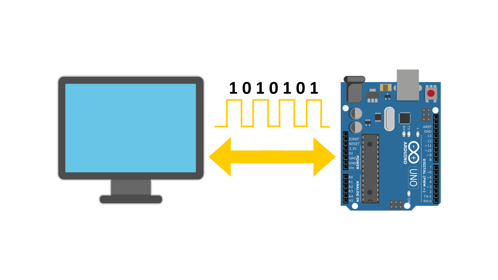
Hello and welcome to Electro Nerds Academy! In today’s tutorial, we’re diving into the fascinating world of serial communication, exploring how data travels between your computer and an Arduino. If you want to learn about the nitty gritty of serial communication then sit tight as this guide is just for you.
Parallel Communication Vs Serial Communication:
Let’s start with a basic scenario. Imagine you want to send the letter “A” from your PC to an Arduino. Computers don’t deal with letters directly—they solely understand binary data. So this letter “A” will be converted into its binary (01000001).
Wondering how we convert the letter “A” into binary 01000001 ??
Step: 1 (Converting letter “A” into its equivalent ASCII code): Every character in computing whether it be letters, numbers, special characters, control characters, all of them are represented by a numeric value this numerical value is called its ASCII value. ASCII stands for American Standard Code for Information Interchange. below is a table showing ASCII values of a bunch of characters. From this table we can determine the ASCII value of the letter “A” which is 65.
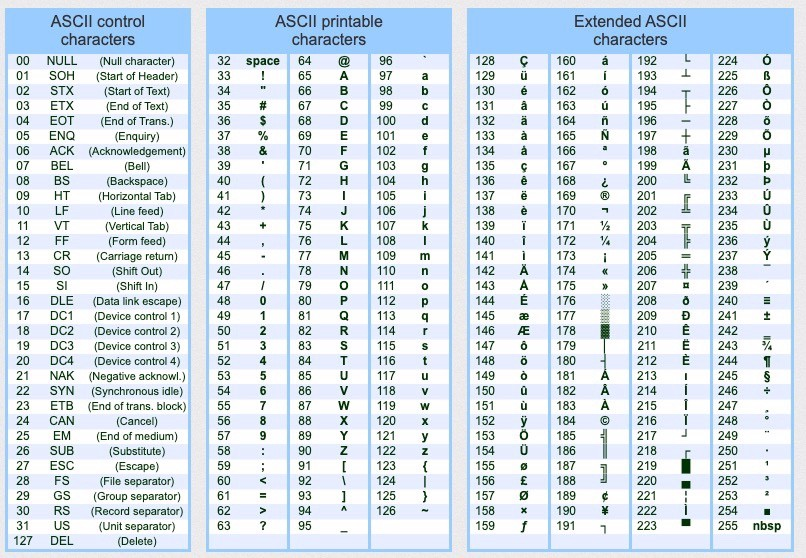
Step: 2 (Converting the ASCII value ’65’ Into Binary): Once we have the ASCII value (which is 65 for “A”), we can convert this decimal number into binary.
65 in decimal = 01000001 in binary
We can see that the converted binary number has eight binary digits or ‘bits’. Now we have to somehow transmit these 8 bits to our Arduino. We can use one of the two methods describe below to achieve this task.
Method: 1 (The Parallel Way)
One way to transmit these 8 bits is through parallel communication, where each bit gets its own wire. So, sending “A” would require eight separate wires, with each wire carrying either a high (1) or low (0) voltage signal simultaneously.
But what if we want to send 16-bits of data, we’d need 16 wires. For 32 bits, we’d need 32 wires and so on. This method quickly becomes impractical as we increase the number of data bits.
Method: 2 (The Serial Way)
Another method of transmitting data from our PC to our Arduino is called serial communication—In this method, instead of transmitting all bits simultaneously, they’re arranged in series and conveyed one by one through a single cable. This approach is more efficient as the number of required connections are reduced thereby reducing the cost, but it is slower than parallel communication.
The role of Clock Signal
To understand why serial communication is slower than parallel communication, we will have to introduce the concept of clock signal in digital electronics. A clock signal is basically a timing signal that is shared between both the sender and the receiver. This signal oscillates between high and low states at a consistent frequency. This signal maintains synchronization between the sender and the receiver. The sender will send data at each rising edge of the clock signal, Meanwhile, the receiver will read that data from the data line at each falling edge of the signal.
So in parallel communication, when the first rising edge of the clock signal occurs, the sender transmits all eight data bits simultaneously on their respective data lines, which remains unchanged until the next rising edge occurs. Consequently, when the first falling edge of the clock signal occurs, the receiver reads or samples the data on all eight wires with just one clock pulse.
Whereas in serial communication, the sender sends a single bit of data at each rising edge of the clock signal, which is then read at each subsequent falling edge by the receiver. As this process repeats for eight bits, serial communication ends up being eight times slower than parallel communication in this scenario.
So Although serial communication is slower than parallel communication, it is still more efficient than parallel communication due to its lower cost, fewer wires, reduced interference, and ability to transmit data over long distances.
Types of Serial Communication:
In general Serial communication can be divided into two main categories: synchronous and asynchronous serial communication.
1. Synchronous Serial Communication
🔹 Shared clock between sender and receiver.
🔹 Data is transmitted in sync with the clock signal.
Examples:
🔸SPI (Serial Peripheral Interface)
🔸I2C (Inter-Integrated Circuit)
2. Asynchronous Serial Communication
🔹 No shared clock between sender and receiver.
🔹 Data is sent with start and stop bits to mark the beginning and end of transmission.
Examples:
🔸UART (Universal Asynchronous Receiver/Transmitter)
🔸RS-232
In this lesson, we’ll focus on asynchronous communication, specifically the UART protocol, commonly used with Arduino.
UART(Universal Asynchronous Receive/Transmit) Protocol
UART (Universal Asynchronous Receiver and Transmit) is a hardware protocol that facilitates serial communication between two devices without the need for a shared clock signal. But the absence of a clock signal in serial communication poses specific challenges between the sender and the receiver.
Problem 1: How does the receiver know when the transmitter is about to send data?
Solution: To solve this problem, asynchronous communication protocols like UART use a standard data frame that includes a start bit and one or more stop bits. The start bit signals the beginning of a data packet, alerting the receiver to start reading, while the stop bit(s) mark the end of the packet. We will discuss the structure of the UART data packet shortly.
Problem 2: How can the receiver determine that in a data packet when one bit ends and the next begins?
Solution: To address the second problem, both the transmitter and receiver are configured to operate at a fixed baud rate—a predefined speed measured in bits per second (bps). This shared baud rate ensures that both sides sample the data at consistent intervals, allowing the receiver to correctly identify the boundaries between individual bits. We will discuss transmission speed (baud rate) shortly.
The Structure of a UART Data Packet
When both sender and receiver agree to use the UART protocol for communication, then the data is transmitted in the form of structured data packets. A typical UART data packet looks like this:

A typical UART packet consists of:
🔹Start Bit:
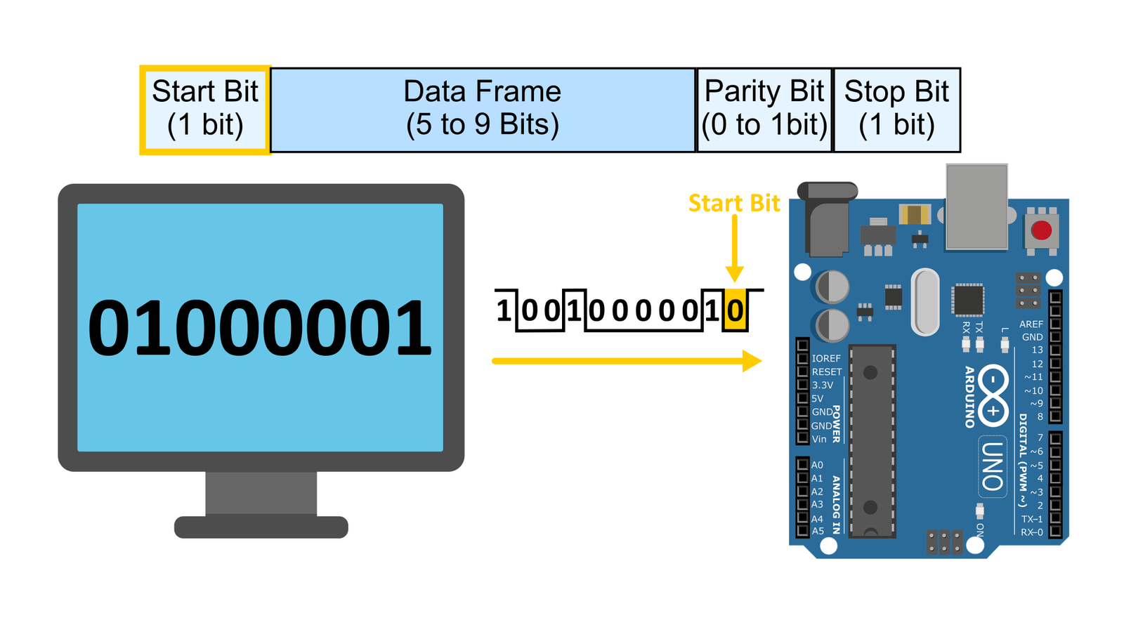
First we have the start bit, normally when the transmitter has no data to transmit, it outputs a HIGH signal. but, when it’s ready to send data, it initiates transmission with a start bit—a LOW signal pulse—signaling the beginning of data transmission. It’s like alerting the receiver, saying, “get ready, I am sending some data”.
🔹Data Bits:
The start bit is followed by the data bits which are the actual data bits that we want to send. So imagine if we want to send a letter A then this letter will be converted to binary and its binary equivalent becomes the data bits for this particular data packet. The data can be 5, 6, 7, 8, or 9 bits long, but 8-bit data is the most common. Usually both the sender and the receiver agree upon the length of the data bits in advance.
🔹Optional Parity Bit:
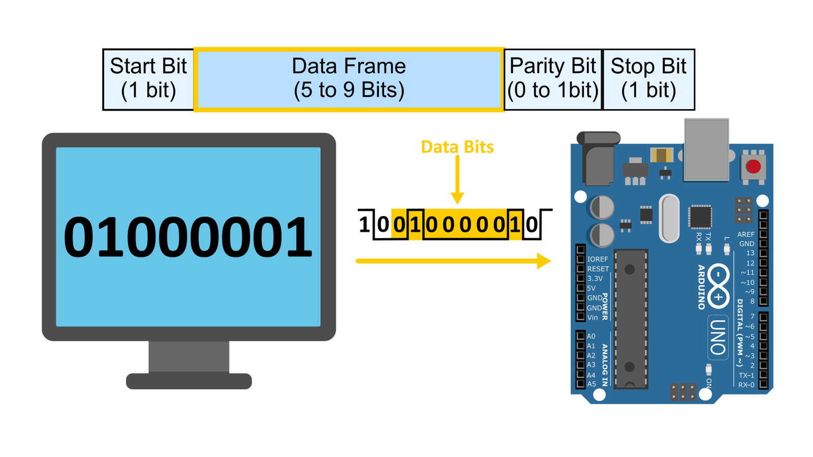
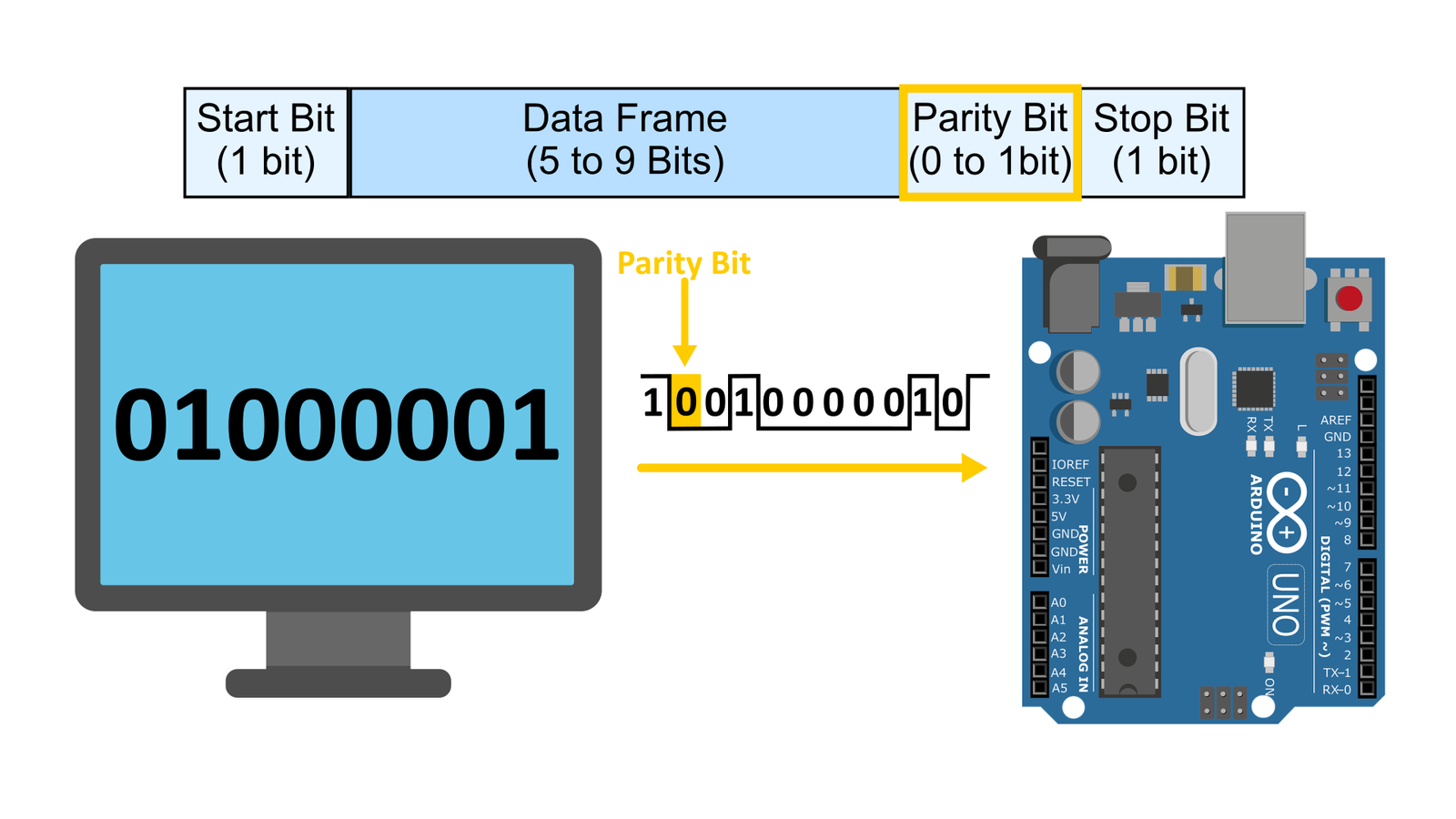
After the data bits, we can optionally include a parity bit. Its role is to inform the receiver whether the data packet is corrupted or not. Here’s how it operates: both the receiver and transmitter must decide in advance on the type of parity they’ll use—either even or odd.
Let’s consider using even parity, which means that the total number of ones in the complete data packet should be even. So, if the total number of ones in the data packet are even like in this case then the parity bit will be zero.
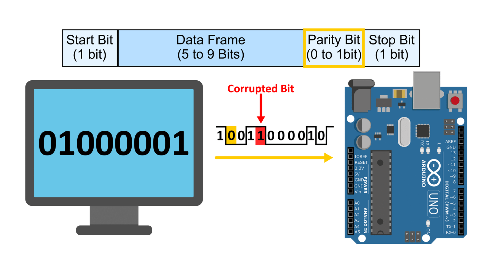
And during transmission, if the message becomes corrupted and one bit’s value changes from 0 to 1, then the receiver will detect odd number of ones in the data packet. Since they both agreed upon using even parity meaning that the total number of ones in the data packet will be even, the receiver concludes that the message is likely corrupted.
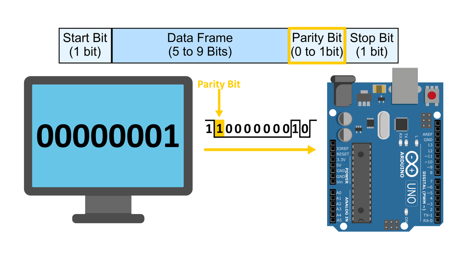
But what if the total number of ones in the data packet are odd? Like in this case shown below. Then the parity bit is set to 1 to ensure that the total number of ones are even. However, it’s essential to acknowledge that this error detection method has its own limitations. For instance, the parity bit itself can be corrupted or if more than one bits are corrupted, then the resulting number of ones will still be even.
🔹Stop Bit:
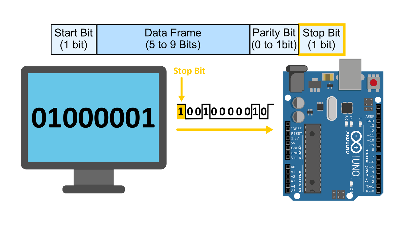
After the parity bit, the next bit is the stop bit, indicated by a high signal, denoting the completion of the message and the end of the data packet.
Transmission Speed (Baud Rate)
Another crucial part of every asynchronous protocol is the transmission speed, that is the speed at which the data packet will be transmitted. The transmission speed is measured in bits per second. A common speed is 9600 bits per second, signifying that 9600 bits are sent in a single second. This translates that each bit takes a duration of 1 divided by 9600, which equals approximately 104 microseconds to travel from the sender to the receiver. To avoid errors in communication, both the sender and receiver must agree on the same transmission speed beforehand.
How Arduino Handles UART Internally
Now, let’s conclude all of our discussion so far and see what happens when we transmit the letter “A” from our PC to Arduino using UART protocol at a speed of 9600 bits per second, meaning that the width of each bit will be 104 microseconds. firstly the letter “A” is converted into its binary equivalent and then this 8 bit data is placed into a data packet with start, stop and parity bits. remember the number of data bits, type of parity is decided in advanced between the receiver and the transmitter.
Communication begins when the transmitter sends a start bit, signaling the beginning of the data packet. Once the Arduino detects this start bit, it begins counting time. After 104 microseconds, it reaches the first data bit’s position. However, instead of reading it immediately—since the signal might still be stabilizing—it waits an additional 52 microseconds to reach the middle of the bit duration before capturing its value. It again counts 104 microseconds to reach the middle of the second bit, reads the second bit, and repeats the process for subsequent bits, ensuring accurate data reception.
As data bits stream in from the computer, a specialized hardware component called USART inside the ATmega328 microcontroller assembles every 8 bits into a byte and stores them in the serial receive buffer—a temporary memory area that can hold up to 64 bytes. From this buffer, we can read the data one byte at a time.
The hardware responsible for assembling incoming bits into bytes is called the USART (Universal Synchronous Asynchronous Receiver and Transmitter). The USART module handles UART communication on the ATmega328 chip. It uses the TX and RX pins of the ATMEGA chip to transmit and receive data serially, which correspond to pins 1 and 0 on the Arduino Uno board. So basically our computer is connected to the USB jack of the UNO which is linked to another microcontroller—ATMEGA 16U, which in this case acts as a USB-to-Serial converter. It takes the incoming USB data, converts it to serial data, and transmits it via the RX pin to the ATmega328. The same path can be followed when the Arduino sends data to the PC, that is the data will be transmitted via the TX pin of the ATMEGA chip to the ATMEGA 16U microcontroller which in this case acts as a Serial-to-USB converter and converts our serial data into USB format and sends it to the PC via the same USB jack.
Conclusion:
🔹In this lesson, we explored the fundamentals of serial communication, highlighting how it differs from parallel communication.
🔹We discussed the role of clock signal in serial communication
🔹We discussed the types of serial communication synchronous and asynchronous serial communication
🔹We discussed asynchronous communication protocol UART
🔹Also we learned how UART solves the challenges of communicating without a shared clock signal.
🔹We also examined the detailed structure of a UART data packet
🔹We discussed the importance of baud rate in serial communication.
🔹Finally, we looked at how the Arduino Uno handles UART communication


