Lesson 2: Blinking An LED

Introduction:
Hello and welcome to Electro Nerds Academy. In this tutorial, we will take our Arduino skills up a notch by blinking an LED—but this time, we will make an external circuit instead of using the onboard LED like we did in the previous lesson. This project will introduce essential electronic components and basic Arduino programming concepts, so let’s get started.
Understanding Circuits:
So before making the circuit for our blinking LED Project. Lets first understand the basics of a circuit. A circuit is a closed-loop path that allows electric current to flow. It consists of:
🔸Power Source – Provides the electrical energy (e.g., Arduino or battery).
🔸Conductive Path – Wires or circuit traces that carry the current.
🔸Load – A component that uses the electricity (e.g., LED, motor).
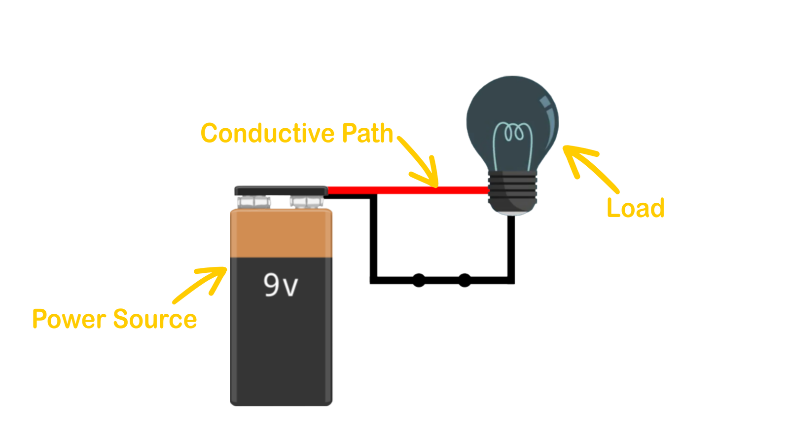
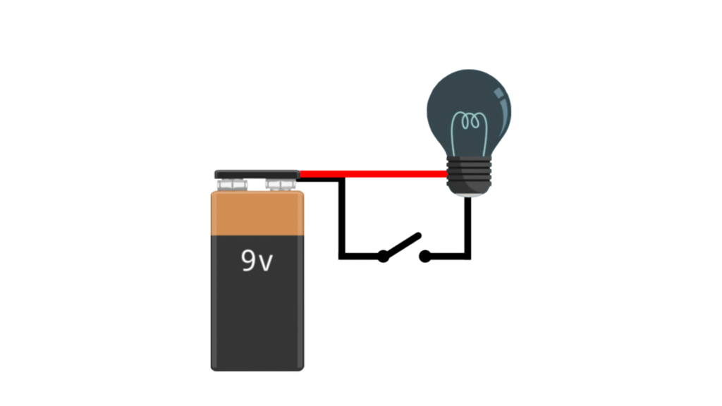
Depending on whether the path is complete or broken, a circuit can be classified as open or closed.
🔹Closed Circuit (Complete Path):
A closed circuit is one in which the electrical path is complete, allowing electricity to flow from the power source, through the load, and back.
🔹Open Circuit (Broken Path):
An open circuit occurs when there is a break in the electrical path, preventing current from flowing.
Components You’ll Need
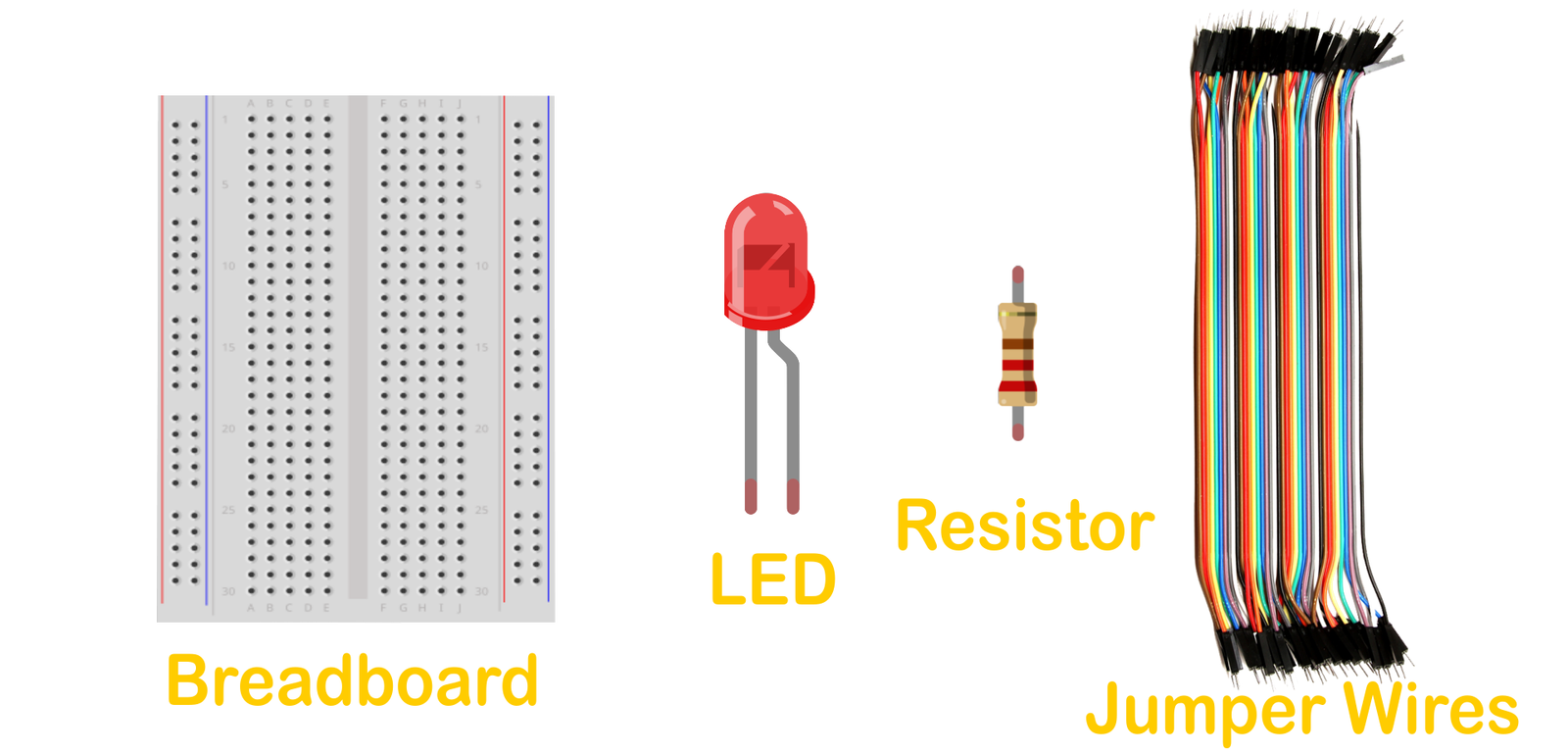
Now that we understand circuits and how they work, let’s start building our circuit for the blinking LED project. For this We’ll use the following key components:
🔸Breadboard – A tool for assembling circuits without soldering.
🔸LED (Light Emitting Diode) – Emits light when current flows through it.
🔸Resistor (220Ω) – Limits current to prevent the LED from burning out.
🔸Jumper Wires (Male to Male) – Connect various components to form a circuit. They can be thought of conductive paths for the circuit.
Building the Circuit
Now that we have all the components with us lets build our circuit, The connection diagram is shown below.
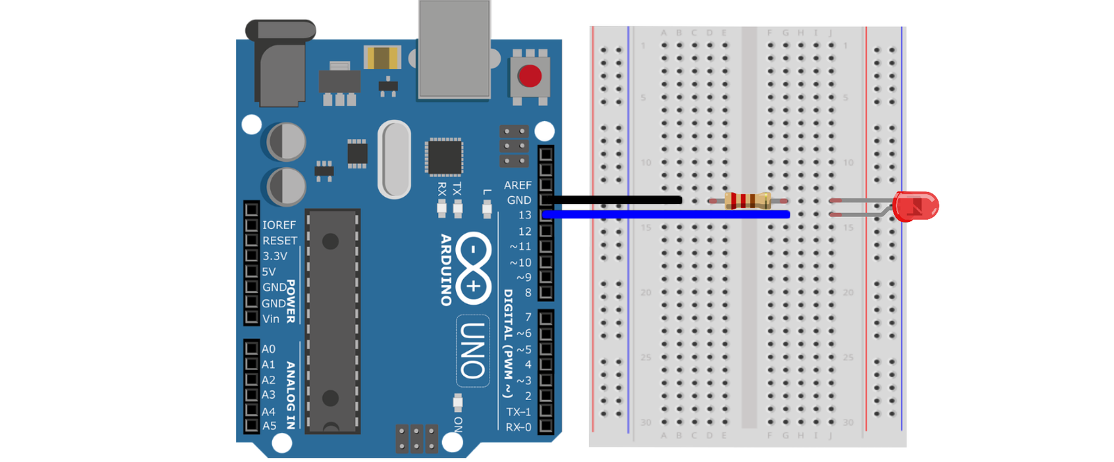
To make the circuit, Follow these steps carefully:
1️⃣ Insert the LED into the breadboard. If you’re new to breadboards, we recommend reading our guide on Breadboard Basics first!
- The longer leg (anode) will be connected to positive voltage.
- The shorter leg (cathode) will be connected to ground.
2️⃣ Connect the Anode of the LED to Pin 13 on the Arduino using a jumper wire.
3️⃣ Attach the Resistor (220Ω) in series with the cathode of the LED and ground it to the Arduino’s GND pin using another jumper wire.
🔹 Why a Resistor?
Resistors helps in controlling the current flow. Here the resistor is limiting the current flow so that less current reaches the LED ensuring safe operation of the LED. If we don’t use a resistor the LED will easily get damaged due to excessive current.
How the Circuit Works
🔸When pin 13 outputs 5V, a voltage difference is created, allowing current to flow through the resistor and LED—lighting it up.
🔸When pin 13 outputs 0V, the circuit breaks, and the LED turns off.
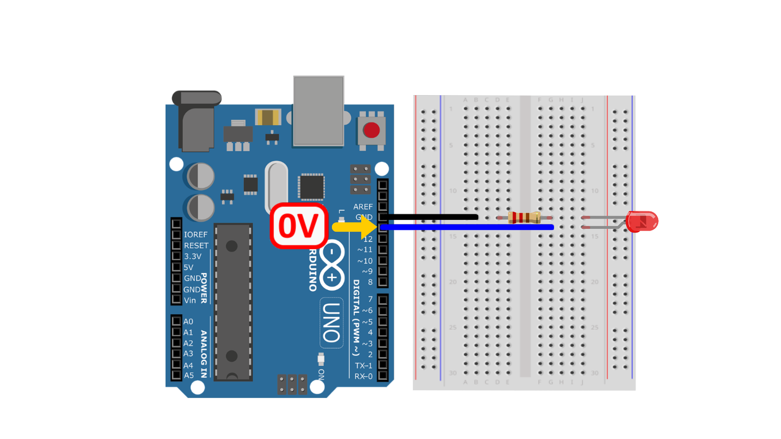
🔸By continuously switching between 5V and 0V, we achieve a blinking effect.
Programming The Arduino UNO
Now that our circuit is complete we will move on to program our Arduino UNO to bring the circuit to life. Every Arduino program follows a specific structure, which consists of two main functions: setup() and loop().
1️⃣ The setup() Function:
This function runs once when the Arduino is powered on or reset. Any code written in between its curly brackets will only be executed once. The code written inside the setup function is used to initialize various settings related to program.
2️⃣ The loop() Function:
This function runs continuously after the setup() function is executed. Any code written in between its curly brackets will be executed over and over again. The main logic of our program will be written inside this loop function.
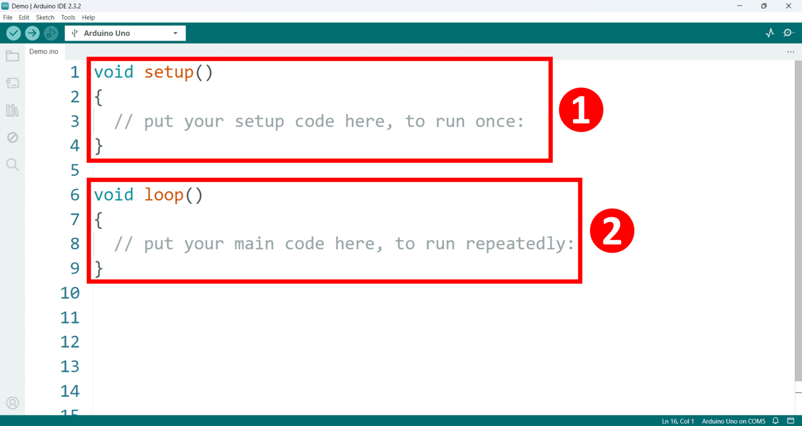
Next we will learn three fundamental functions to initiate our programming journey, If you don’t have an idea, what functions are? don’t worry as we will learn about them in the future lessons in great detail. For now consider functions as commands that tell our Arduino to perform a specific task.
1️⃣ The pinMode() Function
🔹So the first function we are gonna learn about is the pinMode() function. This function is used to define whether a specific pin on the Arduino board will act as an INPUT (reading data) or OUTPUT (sending data). This function is always placed inside the setup function.
Syntax:
The common way of writing this function is shown below,
pinMode(pin, Mode);It takes two parameters which are,
🔸 pin – The Arduino pin number you want to configure.
🔸 Mode – Defines the behavior of the pin. It can have one of the following values,
- INPUT → Used when the Arduino pin is used as an input pin like when we are taking the input from a sensor or a push button etc.
- OUTPUT → Used when the Arduino pin is used as an output pin like for controlling LEDs, motors, or other components.
- INPUT_PULLUP → Enables an internal pull-up resistor to avoid floating values when reading input.
Example Usage:
pinMode(13, OUTPUT);
pinMode(2, INPUT);
pinMode(7, INPUT_PULLUP);
In the example above the first line pinMode(13, OUTPUT); will set Arduino pin 13 as an output. The second line pinMode(2, INPUT); will set Arduino pin 2 as an input. and the third line pinMode(7, INPUT_PULLUP); will set Arduino pin 7 as an input pin with an internal pull-up resistor.
2️⃣ The digitalWrite() Function
🔹 This function sends either HIGH (5V) or LOW (0V) to a digital pin.
Syntax:
The common way of writing this function is shown below,
digitalWrite(pin, value);This function takes two parameters
🔸 pin – The pin number where the signal is sent.
🔸 value – Can be either HIGH (5V) or LOW (0V).
- If a pin value is set to HIGH, it outputs 5V.
- If a pin value is set to LOW, it outputs 0V.
Example Usage:
digitalWrite(13, HIGH);
digitalWrite(13, LOW);
In the example above the first line digitalWrite(13, HIGH); will send 5V to Arduino pin 13. And the second line digitalWrite(13, LOW); will send 0V to Arduino pin 13.
💡 Important Notes:
✔️ The pin must be set as OUTPUT using pinMode() before calling digitalWrite() function.
✔️ If the pin is an INPUT, digitalWrite(HIGH) enables an internal pull-up resistor instead of outputting 5V.
3️⃣ The delay() Function
🔹 The delay() function pauses program execution for a specified amount of time in milliseconds. This function is blocking, meaning the program stops running during the delay.
Syntax:
delay(time);This function takes a single parameter which is,
🔸 time – The duration of the delay in milliseconds (1 second = 1000 milliseconds).
Example Usage:
digitalWrite(13, HIGH);
delay(1000);
digitalWrite(13, LOW);
How It Works: First we have the digital Write function call and we are sending 5V to Arduino pin 13. Next we have the delay function with 1000 written as a parameter value. meaning it will pause the program execution for 1000 milliseconds or 1 second. After this time has passed the Arduino will execute the third line where another digital write function is called but this time we are sending 0V to our Arduino pin 13.
Writing the Code:
Now lets program our Arduino to blink our LED with an interval of 1 second. The code we will be using is shown below, by the way this code is almost identical to the blink example sketch we used in the previous video.
void setup()
{
  pinMode(13, OUTPUT); // Set pin 13 as an output
}
void loop()
{
  digitalWrite(13, HIGH); // Turn LED ON
  delay(1000);            // Wait 1 second
  digitalWrite(13, LOW);  // Turn LED OFF
  delay(1000);            // Wait 1 second
}
Breaking Down the Code:
We start with the void setup function where we set pin 13 as an output pin using the pin mode function. We use pin 13 because we had connected our external LED with this pin.
void setup()
{
  pinMode(13, OUTPUT); // Set pin 13 as an output
}
Then we move on to the void loop function any code written here will be repeated over and over again. Here we first have the digital Write function call and we are sending 5V to Arduino pin 13 to turn the LED “ON”. Next we have the delay function with 1000 written as a parameter value. meaning it will pause the program execution for 1000 milliseconds or 1 second. After this time has passed the Arduino will execute the third line where another digital write function is called but this time we are sending 0V to our Arduino pin 13 to turn the LED “OFF”. Then we add another 1 second delay and the code is completed.
void loop()
{
  digitalWrite(13, HIGH); // Turn LED ON
  delay(1000);            // Wait 1 second
  digitalWrite(13, LOW);  // Turn LED OFF
  delay(1000);            // Wait 1 second
}
So the LED will be first turned ON then we wait for one second and then it will be turned OFF and we again wait for one second and this cycle continues making a blinking effect.
Testing and Modifying the Blink Rate:
Finally lets upload this code to our Arduino. Also note that while the external LED is blinking the on board LED is also blinking as it is also connected to Arduino pin 13.
We can also modify the blinking rate by changing the parameter of the delay function. For a faster blinking rate we will change the delay time from 1000 to 500 and for a slower blinking rate we can change the delay time from 1000 to 1500
delay: 500 milliseconds
delay: 1000 milliseconds
delay: 1500 milliseconds
Wrapping Up:
🎉 Congratulations! You’ve just built and programmed your first external LED circuit with Arduino. If you enjoyed this, explore more tutorials on our website and YouTube channel. And we will see you in the next one.


