Lesson 6: Connecting a Push Button with an Arduino
Introduction:
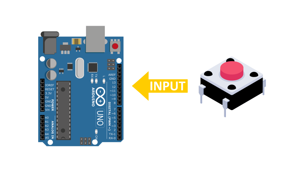
Hello and welcome to Electro Nerds Academy, In this lesson, we’ll explore how to use a push button as a digital input with an Arduino. We’ll build a simple circuit on a breadboard using a push button and an LED and some resistors and our goal will be turn the LED ON when the button is pressed and turn it OFF when the button is released. So lets get started.
What You’ll Need:
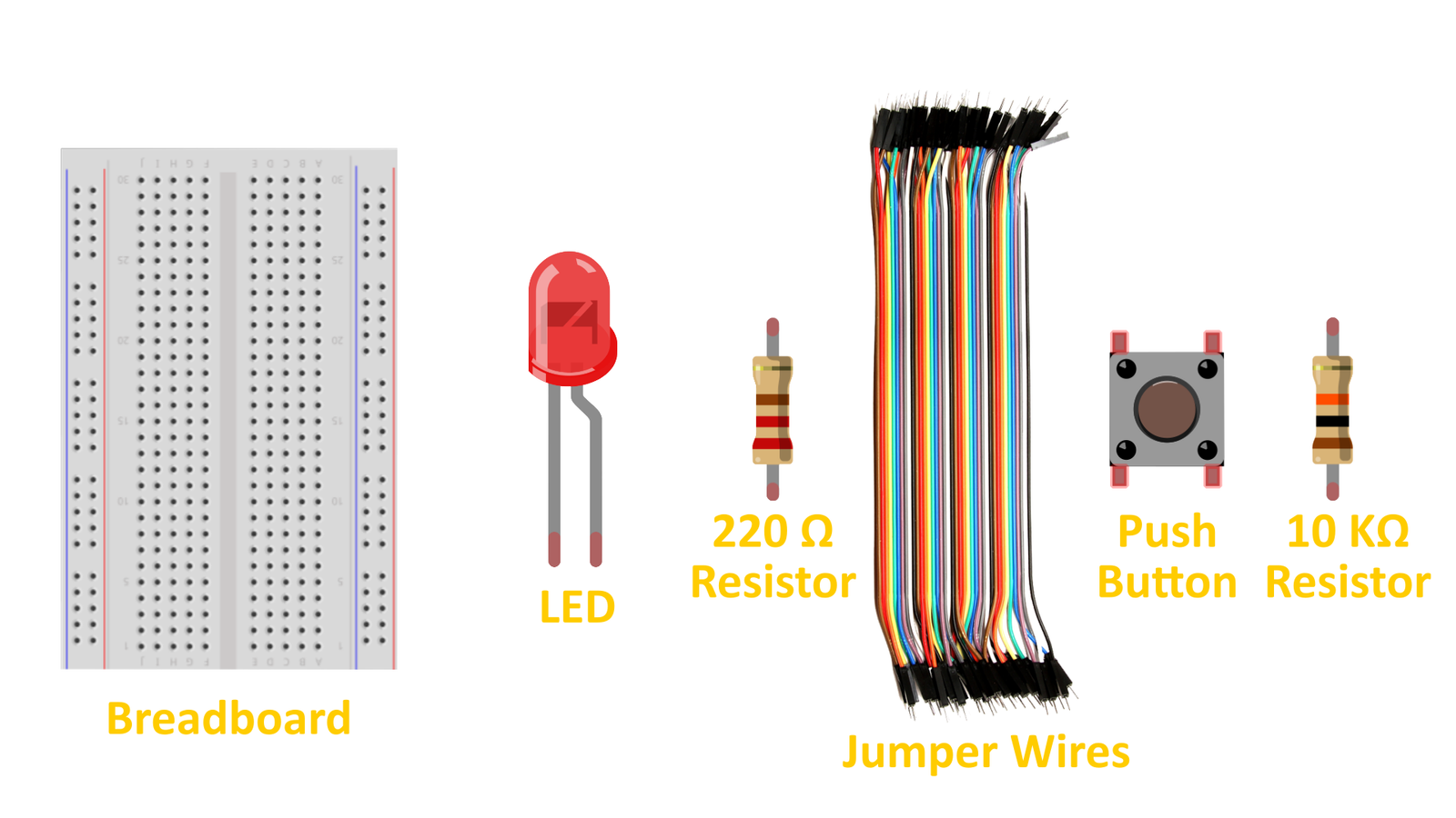
From our custom Arduino kit, gather the following components:
🔸Arduino Uno
🔸Breadboard
🔸LED
🔸220Ω resistor (current-limiting for the LED)
🔸Push Button
🔸10kΩ resistor (pull-down resistor for the push button)
🔸Jumper wires
How a Push Button Works?
A push button has four pins, arranged in two groups. Pins within the same group are always connected.
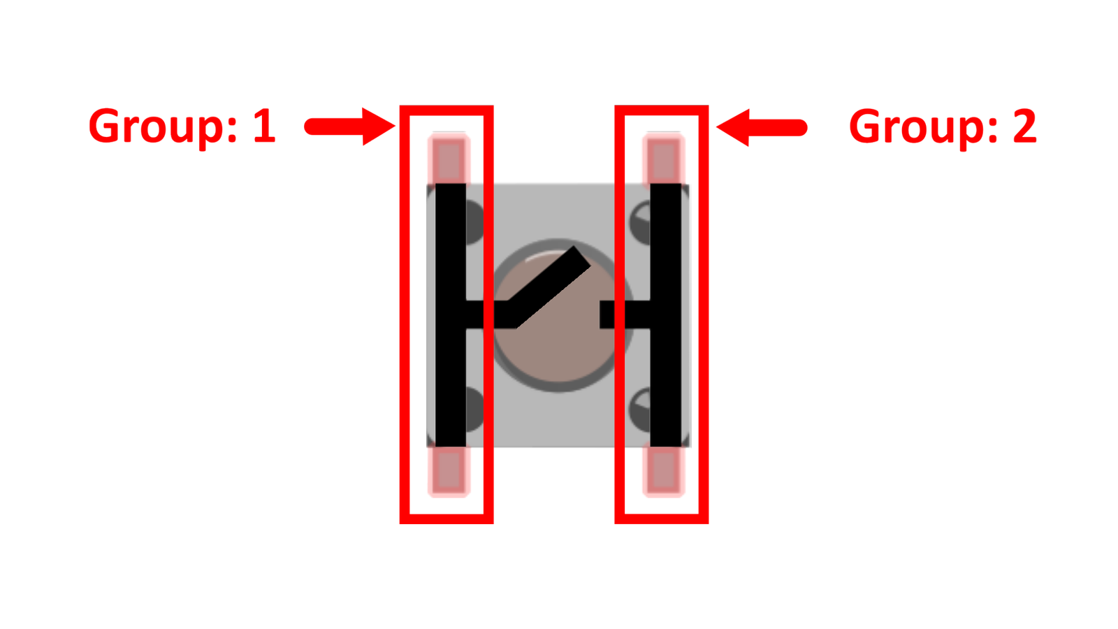
Pins from different groups connect only when the button is pressed.
This means that when the button is pressed, it closes a circuit, allowing current to flow.
Building the circuit
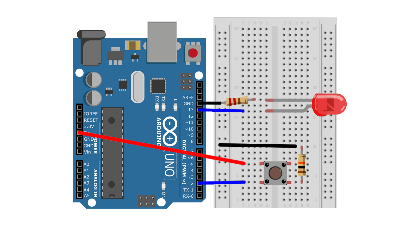
1️⃣ Insert the LED into the breadboard. If you’re new to breadboards, we recommend reading our guide on Breadboard Basics first!
🔸The longer leg (anode) will be connected to positive voltage.
🔸The shorter leg (cathode) will be connected to ground.
2️⃣ Attach the Resistor (220Ω) in series with the cathode of the LED and ground it to the Arduino’s GND pin using another jumper wire.
3️⃣ Place the push button across the middle of the breadboard. Connect one side of the button to 5V on the Arduino.
4️⃣ Connect the opposite side of the push button to digital pin 2 on the Arduino.
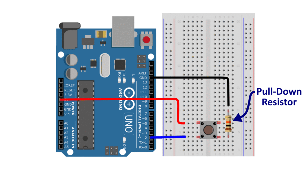
5️⃣ Connect a 10kΩ pull-down resistor from digital pin-2 to GND. This resistor ensures that the Arduino pin reads LOW (0V) when the button is not pressed.
What is a pull-down or pull-up resistor ??
A pull-up resistor and a pull-down resistor essentially serves the same basic purpose in digital circuits: they ensure that a digital input pin reads a definite logic level when no active signal is applied. In the absence of either of these resistors, the input pin is floating meaning it is connected no definite voltage level. A floating input can pick up electrical noise, causing unpredictable behavior (random highs/lows). In this situation a Pull-Up or Pull-Down resistor ensures that the digital input pin reads a definite logic level when no active signal is applied. The key difference lies in which voltage level they default the input to.
A pull-down resistor connects the input pin
to the negative supply voltage (GND).
A pull-up resistor connects the input pin
to the positive supply voltage (Vcc).
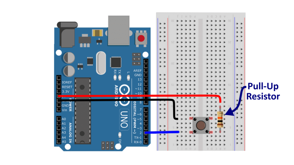
In our case we need to ensure that digital pin 2 reads a definite low logic level (0V or LOW) when no active signal is connected. Therefore we have used a pull down resistor configuration. So when the button is not pressed pin 2 is connected to ground via the 10KΩ resistor and when the button is pressed 5V signal is applied to pin 2, it overrides the resistor, and the pin reads HIGH as expected.
Writing the code
In the previous lesson we had learned about the digitalWrite() function which can output a voltage level 0V or 5V. but here we need a function that can read a voltage level from a particular pin. For this we will use the digitalRead() function.
Understanding the digitalRead() function
The digitalRead() function is used to read the state of a digital pin. It returns one of two values:
🔸HIGH (1) → The pin is receiving 5V (button is pressed).
🔸LOW (0) → The pin is receiving 0V (button is not pressed).
Syntax:
The common way of writing this function is shown below,
digitalWrite(pin);It takes a single parameter (pin) – The Arduino pin number where the signal is to be read.
The function returns the Boolean state of the pin as HIGH(1) or LOW(0). which can then be saved in a variable.
Basic Code:
The basic version of the code is shown below,
int buttonState = 0;      // Variable to store button state

void setup()
{
  pinMode(13, OUTPUT);   // LED as output
  pinMode(2, INPUT);   // Button as input
}

void loop()
{
  buttonState = digitalRead(2); // Read button state
  if (buttonState == 1)
  {
    digitalWrite(13, HIGH); // Turn LED on
  }
  else
  {
    digitalWrite(13, LOW);  // Turn LED off
  }
}
Breaking down the code:
At the top we had declared an integer variable named button state. This variable will store the state of the Button connected to Arduino pin 2.
int buttonState = 0; // Variable to store button stateAfter that we have the void setup function. Where we will initialize the pins used in our circuit using the pin mode function. We will set pin 13 as an output pin and pin 2 as an input pin.
void setup()
{
  pinMode(13, OUTPUT);   // LED as output
  pinMode(2, INPUT);   // Button as input
}
Finally we have the void loop section. Here we will first read the state of the Arduino pin 2 and save its returned value in the button state variable. Next we use an if/else statement to check the state of the push button, If the button is pressed the button state variable is set to (HIGH or 1). Therefore the condition is evaluated to be true and the code within the if block is executed. So we will turn on the LED connected to pin 13 by using the digital write function. However if the button is not pressed the function returns (LOW or 0) which is saved in the button state variable. Now the if condition fails and the code with in the else block will be executed. So we will send 0V to digital pin 13 turning OFF the LED.
void loop()
{
  buttonState = digitalRead(2); // Read button state
  if (buttonState == 1)
  {
    digitalWrite(13, HIGH); // Turn LED on
  }
  else
  {
    digitalWrite(13, LOW);  // Turn LED off
  }
}
The problem of Button Bounce in the basic code
Before you upload the basic code discussed above to your Arduino, We would like to highlight an important point, Basically what happen is that when you press or release the button, the metal contacts inside don’t make a perfect connection instantly. Instead, they vibrate or bounce for a few milliseconds. This can cause multiple rapid presses to be detected, even though you only pressed the button once!
💡 How can we solve this?
We can ignore the extra bounces by adding a small delay after reading the button press. This is not the ideal solution. We will learn a more efficient solution in the future lessons but for now this will do the job just fine. So the revised code looks something like this,
int buttonState = 0;      // Variable to store button state

void setup()
{
  pinMode(13, OUTPUT);   // LED as output
  pinMode(2, INPUT);   // Button as input
}

void loop()
{
  buttonState = digitalRead(2); // Read button state
  delay(50); // <---- Button Bounce Delay

  if (buttonState == 1)
  {
    digitalWrite(13, HIGH); // Turn LED on
  }
  else
  {
    digitalWrite(13, LOW);  // Turn LED off
  }
}
Testing The Circuit
After Successfully uploading the code to your Arduino. You will notice that whenever you press the button the LED lights up.
Conclusion
- We learned how to use a push button as a digital input.
- We used a pull-down resistor to prevent floating values.
- We used
digitalRead()to read the button state. - We solved button bouncing issue using a delay-based debounce method.


